Saturday, September 30, 2017

Making an infill plane from scratch 9, rear infill.

The front infill had a really nice and tight fit yesterday, but apparently the wood is not completely dry, because it has shrunk a bit since then. Not much, but I can clearly feel a difference in the fit. I hope it won't matter too much, but I usually have problems with wood expanding at our place, so it might just end up perfect at home.

To make the rear infill, I sawed out a piece of Bubinga and flattened one side that would serve as a reference for the lay out. This was the lower side of the infill.
Next one side was squared up and finally the last side was made parallel and square too.

Following this I marked out a 50 degrees angle on the forward part of the infill, which will eventually become the frog or bedding for the blade.
If I had had a protractor out here I would probably have used it, but I dont. So with the help of a bit of math and a tangent function I was able to do the job anyway.
After marking up I sawed close to the line with a hacksaw. The surface was then sanded completely flat going through the grits with the sand paper placed on a flat piece of thick aluminum plate.

The block of wood was placed inside the base of the plane and the contours of the side were marked on the wood with a pencil.
The block was removed and a hacksaw was again used to saw near the lines to remove the bulk of the waste.
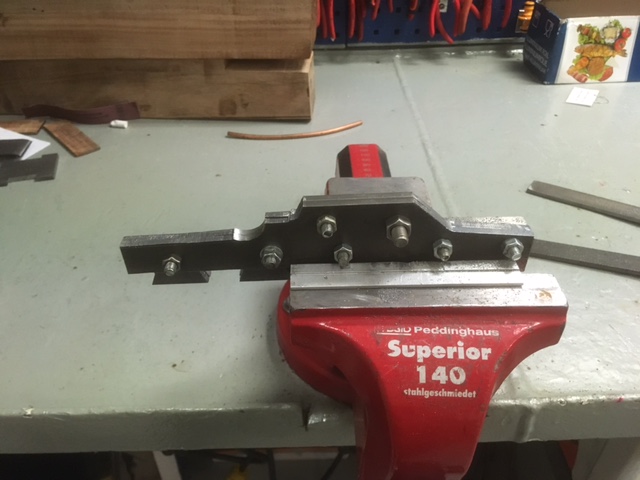
After sawing, the block went back in, and the assembly was clamped in the vice and the wood was brought down to be flush with the sides using files and sandpaper.
Just like with the front tote, I left the rear infill a bit long. This will be trimmed of later.
Making a rear tote is the next part of the project.

Rear infill and front tote.

Rear infill seen from above.


Friday, September 29, 2017

Making an infill plane from scratch 8, front knob and wands

There's not much to be said about the continuation of the build today except that it involved a little bit of filing, and a lot of sanding.
The sanding was done with grit 60 emery cloth, so the surface is not perfect yet, but like the base of the plane, there is no need to make a show surface and risk destroying it while riveting the plane together.
The front knob looks a bit big, but I think it is because the rest of the plane is not yet filled. I made it a bit longer than the base of the plane, so I'll have to trim that when it is riveted in place.

Now that I have gained a bit of experience with the Bubinga, I am going to try to make the aft infill and later the rear tote.

There was a discussion going on in the comment section of one of the earlier posts in this series regarding which type of wand that is best for a woodworker.

I am not saying that the wands from Olivanders' made out of ebony or holly with Phoenix feathers or griffins teeth etc. aren't good, but for woodworking my old time favourite is without any doubt pallet wood with a bit of hair from a Newfoundland dog.

If there should be any sorcerers amongst the readers of this blog, please feel free to comment on your personal favourite wand composition.

Front knob in place.

View from the other side.

Dipped in water to give a bit of shine.

Thursday, September 28, 2017

Making an infill plane from scratch 7, shaping a mushroom.

I found a brand new fine file in our spare tool cabinet, and I used it to make the plane look nicer than yesterday.
I also opened the mouth a bit to the rear of the plane at an angle, so the blade can get through to the bottom and do its job once everything is ready.
Since I will need to flatten the end of all the rivets once the plane is completely assembled, I didn't see any point in going all wild with emery cloth etc. The body is flat and reasonably good looking, so it was finally time for me to get back to some woodworking.

My experience with working this bubinga is very limited, so I decided that it would be a smart move to tackle the front knob or tote first.
I had an idea about making a mushroom shaped knob, and I started by sawing out a block of wood that was slightly oversize.
Once the block was ready, I sketched the outline of the mushroom and the lower part of the knob. I used a hacksaw to saw close to my layout lines, and that way remove the bulk of the material. A coping saw would probably have made it a bit more roundish, but the hacksaw did its job admirably.

I haven't quite figured out how the grain orientation works on this wood, because it seems to be very prone to tear out. But skewing the chisel and working end grain slowly but surely helped getting the shape out.
There is still a long way to go before the front knob is finished, but at least I am back to woodworking which I prefer to filing metal.


Front knob straight from the hacksaw.

Patience and a sharp chisel will eventually get you there.


Wednesday, September 27, 2017

Making an infill plane from scratch 6, assembling the body.

I bolted the two sides together to be able to dress the edges evenly on both pieces at the same time.
There was a little bit of metal left from the sawing, but all in all it went pretty fast.

This was where the exiting part started. There wasn't really much more I could do except trying to assemble the pieces.
The sides went on with a few taps from a plastic faced hammer, and then it was a question of mustering a bit of courage and start peening the metal.

A couple of small clamps would have been nice, but we haven't got any on this ship, so I found a pair of pliers that could work for the initial holding.
The side that was to be peened was mounted securely in the vice, and I started hammering.
I had no idea if I had hammered adequately, too much or too little, but I could feel that the side had become attached to the sole. After peening all the tails, I was astonished by how solid the plane felt. Like one single unit.
I peened the protruding pins a bit as well for good measure, and then it was back to more sawing and filing..

After quite a bit of work, the plane no longer looked like a hammering exercise, but more like a plane body.
I discovered a few places where the dovetails were not as tight as I would have liked them to be, but overall I am happy with the result.
There is still a long way to go to make it a shiny plane, but at least it has got the shape. A belt sander would have come in pretty handy, but lacking one, a file can still do the job.

I would like to thank Peter McBride for an excellent page with a bunch of useful information on building infill planes. I am sorry that I have forgotten to mention that site before, but it has been a great source of inspiration for this project.


Assembled plane body after first filing.

Plane body.

Dressing the edges.

After peening the metal.


Tuesday, September 26, 2017

Making an infill plane from scratch 5, shaping the sides

I continued my infill plane build by filing the remaining dovetails on the last side of the plane. After a test fit much like on two pieces of wood where you press the parts around half way, I again turned my attention to the sole of the plane.

I filed a tail like depression on the pins, so that I have a recess that I can peen the metal into and lock the parts together.
This was a really quick job.

Next I laid out the shape of the sides and the positions for the holes.
I have decided to deviate from my original idea of a 45 degree angle. Instead I'll aim for a 50 degree angle. That way the plane shouldn't look too much like a Stanley copy.
This meant that I had to alter the measurements of the sides as well. I did it on the fly, and since I won't be making multiples of this plane, it really doesn't matter much what the measurements are, as long as it looks OK.
Oh and the entire plane will be 1/8" lower than on the drawing, because I forgot to take into account that I needed some metal for peening when I made the drawing. So again a small alteration from the original idea.

I honestly hadn't given any thought about the position of the holes for the infills, so I more or less drilled them in the middle of the vacant space above the sole.
The rivets will be 1/4" (6 mm), because we happen to have some round steel bar of that dimension. Since the sides are also made of steel, the rivets will not show very prominently as opposed to a plane with brass sides and using steel rivets. So that is at least one good thing about building a plane like this in a cheap fashion.

Finally I sawed the outline of the shape of the sides. Tomorrow I plan to dress the sides with a file, and try to get everything smooth.

Sides drilled together.

Sides and sole together.
Sole showing the filed "tail depressions"

Monday, September 25, 2017

Making an infill plane from scratch 4, dovetails.

Making the dovetails is pretty much sone the same way in steel as it is in wood.
The only difference is that you use a file instead of a chisel to remove the waste. I used a drill to remove the bulk of it, just like some people do in wood.

After cleaning up all the pins on the sole, I wanted to clean up the mouth a bit too.
This was where I discovered my first mistake: When I had drilled the series of holes for the mouth, I had used a 5 mm drill (9/32"). The small file was just able to go through that opening, but it was not great for flattening or removing a lot of material. If I had only measured the regular files first, I would have used a slightly larger drill.
I managed to rout out the mouth using a 5.5 mm drill (something larger than 9/32" but not 1/4" - this is where my limit of the imperial system seems to be).
At last I was able to clean up the mouth with a regular file, and I did only that. It has not been shaped yet.

Since I made the sole first, I did the "pins first" this time. transferring them to the tail boards was done just like any other set of dovetails. I clamped a batten on the tail board to rest the pin board against while I marked the tails.

More drilling, sawing and filing..

I completed the tails on one side of the plane, and I pressed them a bit of the way. They are tight, so I might have to ease up the corners a bit more before the final assembly.

Dovetails of the infill plane


The logo of the chipbreaker.

Sunday, September 24, 2017

Making an infill plane from scratch 3, Laying out the sole.

I received a comment today from Kevin Brehon. He is also building an infill plane, and he has posted some very interesting considerations regarding his design and the building process as a whole.
You can read his blog post here.

My project is moving forward at a steady pace: The blade, the chipbreaker and the screw all cleaned up nicely after being soaked in vinegar for a day. A really fantastic thing is that the black crust/scale on the steel bar also disappeared after the vinegar bath. So now I have some bare grey steel to work with which is nice.

Yesterday I sat with a piece of paper and tried to make something resembling a construction drawing of the plane. With actual size measurements and angles etc.
I also experimented a bit on the dovetail lay out until I finally arrived at something I believed in.

Today I squared up the three pieces of steel bar and sawed them to the correct length and made sure that the freshly sawn end was filed square too.
I then started laying out the lines on the sole. I started by scratching some longitudinal lines that would define the depth of the dovetails and also define the final width of the plane.
I will end up with the pins being 1/8" proud. That should be more than sufficient for peening, but off course it will give me a lot of material to get rid of in the end. But when working with standard width stock you can't be too picky.

Next I laid out the position of the mouth, but I deliberately made it too small. My idea is that I can open it up later so I can achieve a tight mouth when the blade is inserted.

The dovetails were laid out last. I eyeballed an angle that I found pleasing, and marked the lot of them.

I marked out some help lines and punched some dents with a center punch, to give the drill a starting point.
My idea is that it is faster to drill out material than it is to file it away.

All this actually took the best part of the evening, and there isn't much wow effect in showing a piece of sheet metal that looks like a Ford T after a gunfight in an old gangster movie . But it is all that I have got for you.

Construction drawing with sole all laid out in front.

It really helps that we have a very nice drill press.