Showing posts with label Hand planes. Show all posts

Monday, July 7, 2025

Barnsley hayrake table for my sister in law

 Mettes sister turned 50 this year, and her husband asked me some time ago if I could make a table for her birthday. 

They have recently bought a summer house and wanted a slab table of sorts. 

I showed him some pictures of the tabletop I made a couple of years ago, and some pictures of the Barnsley hayrake tables that I have made. and he confirmed that it was something along those lines that he would like to give her. 

We settled on a family price, and I got the joy of being able to make a complete table this time. Not just the tabletop. 

I wanted to blog about it during the build, but given that it was a birthday gift I couldn't out of fear that the surprise was blown. 


All the wood comes from the blood beech that I milled a couple of years ago, save for the pegs that I used for the drawbores that are made of ash, and the butterflies that are made of elm. 

I had forgotten how much work there is in flattening a massive slab using hand planes, and at one point I considered if I should try to make a flattening jig for a router. But I decided that it wasn't worth the while for just one slab.  

A thing I remembered from last time was that it was important to make the breadboard ends before putting too much energy into the flattening. Simply to keep the split parts of the crotch in place. So that is where I started. 
As soon as the breadboard ends were in place, a regular workout using a jointer plane with a scrub blade in it was the next task. I switched a little with a regular jointer and going either diagonally or traversing the grain. 
The slab had twisted a bit during drying, so one small area in the top end of the crotch kept being about 1/4" lower than the rest of the surface. I decided that it would be a waste of time, wood and energy to remove that much wood from the rest of the slab, just to get everything flat. After all it was an area about half the size of my palm, and I felt that it gave a bit of character to the table. 

I made a bunch of butterflies in progressively larger sizes out of elm, just to give a bit of contrast to the beech. The butterflies serve both to stabilize the split crotch area and to fill up the void so you don't accidentally push a dinner plate through the large hole. 

Once the butterflies were glued in place, they were dressed down to the surface of the tabletop, and I sanded starting with grit 40 on a belt sander and ending with grit 240 on a random orbit sander.

The undercarriage for the table was interesting to make due to the tabletop not being rectangular. I decided that it would look the best if the legs were sort of the same distance from the edges of the table. To avoid any hiccups, I made some full size drawings of each end, so I had something to work from. 
I mounted the two traverse pieces with a tenon through the center, and the traverse piece itself set into the top of the leg (I am a bit uncertain what the technical name of that type of joint is).

After chopping in MMXXV in the lower stretcher, the table got a couple of coats of a wipe on finish (linseed oil, spar varnish and turpentine) And it was moved inside the house to be ready for pick up (and to make a bit of space int he shop again).

As always a challenging and satisfying project. The biggest issues were that he top was heavy and unwieldy, and that it takes up a lot of space during the build. 

I clocked my hours, and all in all there is 60 hours of work in the table.


Wednesday, September 11, 2024

Drydock pallet frame cabinet part 1

 We have a volunteer engineer apprentice on board. She is doing her initial training and is doing a great job. We talked a bit about making stuff one day where she was knitting a sweater. I told her a bit about what I had made earlier of woodworking, and she told me that one of her oldest friends were going to get married - and that she would like to make something for her as a wedding gift.

After discussing the various possibilities and showing her examples from my blog she set her mind on something like the small hanging cabinet with drawers which I made 9 years ago.

As per usual, we started off finding a decent pallet frame so we had some wood to make the cabinet out of. Since we are in drydock at the moment, and due to the nature of our ship, we have a lot of the carpenters machines ready set up in a warehouse on the yard. So stock preparation was much easier than it used to be. We have a small Makita planer that could trim the boards to the desired thickness in very little time. The table saw is out of service at the moment due to someone sawing into a hidden screw and activating the Sawstop. So for the ripping of boards we had to use the band saw.

Klara is new to woodworking, so I decided that a rabbeted construction would be the best bet, also given that we need to complete the cabinet before the wedding.
For some reason we don't have a router plane, so for the dado for the shelf, I had to make a small router plane out of a block of wood and a sharpened screw. That worked OK.
There is a Lie Nielsen rabbet block plane on board that we used for the rabbets. I like my Veritas skewed rabbet plane better, or the old combination plane that I have in my ocean going tool set. I didn't bring this set with me, so we had to rely on what we could find on board.

The case was assembled using some headless brads and glue. We had glued up a back panel which was reduced in thickness to 1 cm (3/8"). The back panel was attached in a rabbet with a dab of glue in the center and some more headless brads. The idea is that the back can then move a bit with the seasons without splitting.

I demanded that the face frame was built traditionally with mortise and tenons and rails and stiles. No mitered corners and quick solutions. Klara really liked the look of the face frame on one of my other old cabinets, where there is a small moulding on the inner part of the frame. In order to make something like that, we found an old moulding plane that someone has once donated to the ship, and it was still sharp enough to work. 

So far we have made one corner of the face frame, but today we are going to see of we can complete it and glue it onto the case.

Klara planing wood for the face frame.

The case with the back panel mounted

Klara using the moulding plane.


Sunday, July 7, 2024

Table extensions for a Barnsley Hayrake table

 10 years ago I made a Barnsley Hayrake table to a friend of mine. The table ended up looking a bit weird since the legs were to close to the ends and the sides, and they were also too large compared to the size of the tabletop, giving it a bit of a clumsy look. 

The problem back then was that I had first been given a size that the table should end up being, and I started constructing the lower part of the table according to that. When I was done with the legs and stretchers and all assembled, my friend suddenly called me and asked how small I could make the table..

She had forgotten to take into account that in order for a table to work, it is fairly important that there is sufficient room for someone to pull out a chair to sit in.

Anyway, about half a year ago, she called me and asked if I could make some extensions for the table. 
I was curious to see how it looked, and I loved the idea of having a chance to make it look a bit more harmonic.
I drove up to see her and took some measurements of the table. the top had shrunk a bit unevenly, so one side was 3/4" narrower than the other end. But all in all the table still looked great.
As luck would have it, I still had a bit of larch left in dimensions that could be used for the extensions.

In order to avoid having to make an extra leg or some swing type support, I chose to make a frame and panel type extension. That way it could be held by just a couple of long sliding sticks underneath the tabletop. Also this meant that the extensions could be removed and there wouldn't be anything to interfere with the knees of the people sitting at the ends of the basic table.

I didn't do any finishing, but she said that she planned on giving it some soap just like the rest of the table had been treated with. 

Trimming of tenons.

Proof to Brian Eve that I still use his old plane :-)

Barnsley Hayrake table with extensions.

Frame and two panels.

Marking up for the holding sticks.

Working on the underside.

All completed.


Friday, March 12, 2021

Details of Gustav's DTC

I asked Gustav to take a few pictures of how his block plane was held in his DTC. He also supplied a few other pictures of details.

The block plane which was a gift from Brian Eve of Toolerable sits on the left side of the chest in the top compartment. The inspiration for the holding arrangement also came from Brian, who has his block plane sitting in a leather pouch in the same spot.
Gustav chose to make his out of wood. Each side is made out of two strips of wood glued together via a triangular piece. The entire holding arrangement was glued and tacked to the side of the chest after the two sides were dry. 

In the other side of the chest, his speed-square is mounted using a piece of wood with a groove in it and a notch in the outer tool rack. The framing square simply sits along the backside of the chest being supported by the narrow slots in the shelves. We had to cut off 1.5" of the long leg of the square to make it fit inside the chest, but It sits very well protected now.

The two drawers are dovetailed with through dovetails. The bottoms are massive wood planed down to 1/4" thickness and held in a groove in the front and sides and overlapping the back of the drawer. We made them the traditional way because I know that once in a while it can be useful to have an example of a drawer to show to people. For instance if you need to show your friends what a dovetailed joint looks like.
The pulls are thin leather straps nailed to the bottom of the front. The straps will bend when the battens for locking the fall front are inserted, and they don't protrude so much that the drawers needed to be made shorter. The notches for allowing the locking battens just need to be a bit deeper to accommodate the folded leather.

Thin strips hold the block plane securely in place


Hultafors speed-square on the side.
Framing square in the back


Dovetailed drawers with leather pulls.


Saturday, July 18, 2020

Making a small ovolo infill plane, 2 dovetails.

Yesterday evening I first removed the remaining waste between the pins. Then I transferred the pins to the sides where the tails were going to be.
Those were sawed out on the edges and a drill removed most of the material. After that a file was used to remove the rest of the waste down to the baseline.
After a little adjustment, the pieces went together as they should.

I used a file for flaring out the backside of the pins, in order to make the "double dovetails". And that was pretty easy. I didn't make a huge flaring, but just enough so that the dovetails will be locked once I peen them together.

When I made the infill smoother a couple of years ago, I made the aft part of the sides with a couple of swooping lines. Or at least that was the thought behind the design. I decided to see if I could make this plane look as though it had some relationship to the bigger plane, by making the same design feature.
It didn't work out at all!
First the drill started wandering off because my design placed two holes too near each other. I thought that I could fix it with a file and still make it look good.
After a bit of filing it became clear that I could not make two small swoops that looked good.
I found a bigger diameter round file and decided on one swoop instead.
The edges turned out pretty well and I was happy until I removed the sides from the vise.
Instead of the elegant shape that I had envisioned, I now stared at the silhouette of a pickup-truck with an extended cab.

To get on from that point, I marked out for the mouth of the plane, and drilled a series of holes where the mouth will be. The holes were then cleaned up with a file. It is a lot easier to drill and file in just the sole on its own, instead of doing it when the sides are connected pickup shaped or not.

I didn't want to start peening the parts together because it was getting a bit late, and I didn't want to disturb anyone, and I also didn't want to risk messing things up.
After working a bit more with the material, I am beginning to think that it might be bronze rather than brass. First it doesn't smell like brass and second it machines differently too. Brass will make a lot of small chippings when drilled, but this makes nice long shavings when drilled. (there is probably a correct word for that too).

The next part will be to work a bit more on the mouth, peen the parts together and start making the wooden infills.


Pickup shaped infill plane.


Proud pins and tails.

I had glued the sides together before filing them.


Thursday, July 16, 2020

Making a small ovolo infill plane

Since I have returned to the blogosphere, I have been thinking about something new to blog about.
The projects that I have made the last year have been completed without any photographic evidence, so I might as well start something new to make out here.

We are currently in dry dry dock, and I haven't brought my tool set with me.
I could go out and use the tools in the carpenters shop, but where would the fun be in that?

Instead I have decided to try and make a small infill plane. We happen to have some sheet brass on board, and That should be a "heckuva" lot easier to work compared to my last infill plane which was made out of regular mild steel.

As I predicted when I completed the last infill plane, I haven't used it a single time since I made it. But that is because I have a nice Stanley Bedrock #4 that I use as my everyday plane at home.
I haven't got a functioning ovolo plane though, so merging an infill plane with a moulding plane should be a fun little experiment.

I drew a rough sketch which sort of gave me the overall measurements of the plane. It will hopefully end up being sort of 4.75" long and 1" wide. The height of the sides will be around 1.5"

First I marked the outline of the sides and the bottom on the sheet of brass, and then I used a hacksaw to saw them out. The sides were held together in the vice and filed to the same overall size.
The bottom just had one side filed smooth.

Using the smooth side of the bottom, I marked the two baselines for the dovetails, Doing it that way should in theory result in that any deviations in width will be on one side only, and I won't end up with a wedge shaped plane.

The brass is 4 mm thick which is pretty close to 5/32". in order to make sure that there will be enough material to peen, the pins will be 1/4" long.

I marked out for a half pin on each end of the bottom, and two full pins in between them. A bit of sawing followed by some drilling removed most of the waste. I started filing one end, but decided to stop for the evening instead of stretching it too far.
It feels good to be back at making something like that again!


Starting to file the waste away.

Dry mock up of the plane to be.

Wednesday, August 22, 2018

Thank you Ralph

Suddenly one day during my home period (which ended yesterday), the mail man (a woman actually) stopped by and delivered a package.
It was addressed to me, but I hadn't ordered anything, so I was puzzled, and Gustav and Asger immediately asked what I had ordered.
When I told them that I had no idea they became really curious.

The package was sent from USA, and contained a beautifully restored Sargent plane from Ralph  the accidental woodworker.

In the very nice accompanying letter he explained that no one on his side of the pond were interested in such a plane, so he wanted to give it to our youngest son Asger to use, since he likes to spend time in the workshop with me.

Due to a busy schedule, we never got to trying the plane out, but based on last time Ralph sent a tool my way, I am certain that it will be a joy to use.

So Ralph, thank you so much for the nice plane and for thinking of Asger. And sorry for not having posted any sooner, but we were really busy with a soccer tournament of 4 days and after that a horse tournament also of 4 days, followed immediately by getting back to school. So the plane had to wait a bit.


Asger unpacking a Sargent plane from Ralph.

Christmas comes early this year.


Saturday, May 12, 2018

Smith & Wesson 629 presentation case 3, dovetails and assembly.

Laying out dovetails is normally fairly straight forward, but I had to think hard on this set, because of the plan to glue up all at once, and then split the box to form the lid and the base.

I had to incorporate two grooves, and I also wanted the split pin to be the correct size after splitting and planing.
In the end I managed to make a layout that suited me. I also need to take into account that my narrowest chisel is 1/4".
So I can't make those ultra thin pins even if they would look fine on a project like this.
I made a template for laying out the angles of the dovetails, and I settled on 1:8 sine it is hardwood.

Before dovetailing, I did something unusual (to me at least). I used by shooting board to trim the ends to the become square and the pieces to become the exact same length.
I felt that I had to use this approach, since the stock is thin, so I couldn't just plane away to remove inaccuracies later on as I normally do out here.

Since the pieces were comparatively small, I was able to do it tails first, which I prefer. The actual chopping out was done on a piece of wood held in the vice, and then with the work piece clamped on top of that.

Once all the dovetails were completed, and I had dry assembled the case, I made the rabbets on the lid and bottom, to make them fit in the grooves.
I have never had much success with the small nicker when going across the grain, so I tried instead to first score a line with a hobby knife.
Then after every two passes or so with the plane, I would score another line to keep the rabbet looking good. It took a bit longer than if I had just planed the rabbet, but it looked so much better, so it was definitely worth it.

The rabbet along the grain was a walk in the park. A sharp iron does the trick.

Based on Sylvains comment to the last blog post, where he asked if it was possible to change the fence to the other side, I had decided that I could try to make a new set of rods that would allow me to do just that.
The engineer apprentice on board will soon attend his exam, and he needed a bit more routine in using a lathe. So I made a drawing of some rods that would work, even if we didn't have the correct tap and die for making the same thread as what is originally in the plane.
He made two parts, and I made the remaining two, so I could use the plane tonight.
It is not a 100% elegant solution to use the plane the other way, but it works, and the is the most important thing.

So after making the extra set of rods, I planed the rabbet that would have been against the grain, but now wasn't anymore. It worked brilliantly.

Again I made a dry assembly, this time incorporating the two panels. One of the panels needed to have one side trimmed with a single swipe of a plane, to make it slide easier in the groove.

The edges between the rabbets and the top were rounded to soften the look.

Glued up box.

Shooting the ends.
 
Workholding for chopping out dovetails.

Record No 50 with fence on the "wrong" side

View from underneath. The wooden fence was needed so I could plane with less than the full width of the iron. The depth stop is a fence (I can't remember for what use) that has been flipped 180 degree

Dry assembly of the box.


Wednesday, May 9, 2018

Smith & Wesson 629 presentation case 2, getting groovy

The build continued today with a bit of work on the sides and and ends of the presentation case.

First I straightened one side of all pieces, and then I marked out for the final height of the box.
I ripped the pieces slightly over sized, so I could plane them to the final dimension. I made sure to keep an eye out for grain orientation which helped a lot.

I marked the individual pieces with some carpenter's triangles, and again I made sure to keep an eye out for grain direction , since I had to make some grooves on the inside of all the pieces.

After looking at the top and bottom, I decided to use the 1/4" grooving iron. It was the same one that I had sharpened last time I was on board, so I knew that it would work.
The iron was installed in the combination plane, and I made a few test swipes on a piece of scrap, to check if was adjusted OK. It might have been sheer luck, or it could be that I I am slowly getting better at setting up the plane - but anyhow the plane took a nice crisp shaving right from the start.

For the first grooves the workholding wasn't a big deal. I clamped a large piece of wood in the vise, and used some clamps to hold the pieces onto that large stick.

The challenge came when I had to make the set of grooves destined to receive the bottom of the case.
I couldn't turn the pieces around and plane from the other end unless I wanted to effectively ruin it all with tear out.
So after a few experiments I made some sort of a sticker board, and planed the bottom grooves from the same side.
I managed to make some really nice and crisp grooves on all pieces, and there was practically no tear out. It is nice to see that a little forward thinking on grain direction actually can help.

The next step will be to cut the sides and ends to their final length and shoot the ends of those pieces, when that is done I am going to lay out some dovetails.

Planing all pieces to the same height.

Workholding for the bottom grooves.

Sides and ends with grooves.

Sunday, May 6, 2018

A Barnsley hayrake table 4, final assembly.

The breadboard ends were sawed flush to the side of the tabletop, and the top was then flipped over so I could smooth the underside first.
Planing such a large glued up top of larch was something I attempted last time I build the table, and the results were not good at all. So this time I decided to start with what I knew would work: A portable belt sander and some 40 grit bands.

Once the underside was smooth and flat, I sanded the sides and ends and chamfered all the edges on that side with my small Japanese chamfer plane. I flipped the top over again, and the I made some buttons out of elm to attach the table top to the base with.

The tabletop was then mounted in the correct position, and I sanded the top side with grit 40, 60 and finally 80.
The edges on this side were chamfered too, and that as they say - was that.

I tried taking some glamour shots of the completed table, but my photographic skills are as you know not the best. Furthermore the table is so large that it is difficult for me to get a proper distance for taking good pictures without any disturbing things in the picture.

I have logged all the time that I have used on the table, and I was a bit surprised, that it took me longer to build than the first hayrake table a couple of years back. I think that the difference is that I made breadboard ends on this one, and also the classic way to attach the upper cross stretcher.
The time totaled at 49 hours and 10 minutes, efficient work time that is. If I had to go see why Bertha was barking, or to get a cup of tea, the clock was stopped.

Personally I think that this table looks a lot better than the first one, especially since the size of the top fits better to the base. And I also really like the look of the breadboard ends.

While it isn't of great importance how long time it takes to build something, I like to monitor it due to my own bad memory.
In case someone sees the table and thinks that it looks nice, and asks me if I could make one more, then I would like to remember just exactly how long time it took me, so I don't accidentally say that oh, I can make one of those in a long weekend in the shop.


Barnsley hayrake table, 10' x 4'

Longitudinal stretcher to crosspiece in hayrake.

Crosspiece to arms of hayrake.

Hayrake to legs.

Japanese edge nicer (chamfer plane)

2018 (plus sack of garbage behind stretcher)

Breadboard end.


Friday, March 30, 2018

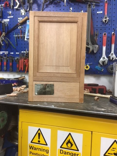
Pilot ladder cabinet 9, door and metal plate position.

We have had a couple of days in harbour, and due to the Easter, we have had a chance to relax. For me relaxation means going in the workshop and continuing with the build.

I completed the door for the cabinet, and there was quite a lot of work involved. I have brought a copy of "The essential woodworker" with me, and Charles Hayward suggests that to ease the look of a panel type door, the inside edges should be broken by either planing a chamfer or by some sort of decoration.
After a bit of consideration, I opted for making a small beading on the inside of the frame. Before starting, I honed the blade for the Record No 50, and adjusted it for a fine cut. Despite one of the sides not being 100% with the grain, the beading came out a lot better than I had anticipated. Having a beading made the rest of the joinery a bit more complicated, but after some fiddling, the frame was ready.

Of all the panels that I had glued up in the start of this project, I had chosen the flattest and most uniform looking for the door panel. I could see that it was a bit too narrow, so I glued on a small piece left over from the drawer bottom. It was close in colour, and wide enough to give me the size I needed plus a bit extra.

I like raised panels on doors, and I have made one on board a ship some years ago. I wanted to replicate the method and it worked out just as well this time, despite the wood being a lot less cooperative compared to soft spruce.
The method I used was to initially plow grooves and dadoes along the edges of the panel, to define the raised center. These grooves/dadoes are probably a bit less than 1/8"- I never measured them. 
I make the grooves so wide that my smoothing plane will be able to overlap the flat bottom of the grooves. So for my wooden plane that means a width of 3/8".
The next step is to clamp a batten along the grooves/dadoes for the smoother to register to. Then it is just a matter of holding the plane at an angle and remove some material.

Once all the planing is done I lightly sanded the raised panel to remove a few marks. Mainly on the ends where I had traversed with the plane.
In an uneventful glue up, the panel was mounted inside the frame, and later the horns were removed from the stiles.

Metal plate position:
I have been giving quite some thought to the idea about the metal plate from the pilot ladder.
-My first idea was to put it somewhere hidden on the inside. Other people (including my daughter) suggested that it should be mounted boldly on the front. 

Now if I put the plate on the inside, it will hopefully end up looking like a nice cabinet, that maybe my dad, Olav and whomever I have of woodworking friends will notice and perhaps look at and comment on.
Most other people I know will likely see a small cabinet and never give it any further thought.

If I on the other hand put the shiny metal plate on the front, it will almost certainly attract attention from a lot more people. Who I imagine will go and look at the cabinet and read the label that seems to be out of place. That could likely lead to a series of questions about the cabinet, and that could be interesting.

It isn't complying with Shaker tradition, to boast of something that you made yourself, but it might be an eye opener to some people, that it is still possible to make things with your own hands that looks OK, and that all upcycling doesn't have to involve white paint and some rough boards.

As a experiment, I placed the door and the drawer in place in the carcase, and mounted the small metal plate with some tape, to get an idea of how it could be mounted.
If you have an opinion on the matter regarding if the plate should be mounted as a sort of peoples fishing lure (to attract attention) or not, I would like to read it in a comment.
I would also like your opinion on how the plate should be positioned if you think that it should be displayed prominently. 


Cabinet with no metal plate
Plate mounted horizontally on door.

Plate mounted vertically on door (similar to raised panel)

Plate mounted on drawer.
(technically it could go in the center of
 the drawer, but that would require
 two pulls instead of one center pull)

Grooving /dadoeing the raised panel.

Position of plane to make the raised panel sides.

Glue up of door.