Wednesday, March 16, 2016

Making saw nuts

Several readers (OK two) asked if I could write a post about how I make my own saw nuts.

My blog has been accepted to such prestigious places as Unpluggedshop.com and norsewoodsmith.com, both places dedicated to hand tool blogs.
I hope I won't get expelled by having a single post where the majority of the work is done at a machine. And it isn't even woodworking.

As Jeremy cleverly remarked, having access to a metal lathe is step 1. But if you have got that, there is no reason why you shouldn't make your own saw nuts. I won't go into details about how to use a lathe, but merely show step by step how I have done it.

Corresponding text is written below each picture.


A finished set of screws and nuts for a children's saw.


Making a saw screw:

Step 1) 
I turn the overall dimensions with a roughing tool. This leaves some angled transitions where the diameter changes


Step 2)
I removed the angled transitions with a parting tool.


Step 3)
A square is made using a file.


Step 3) 
View from a different angle.


Step 4)
Cutting a thread with a die.
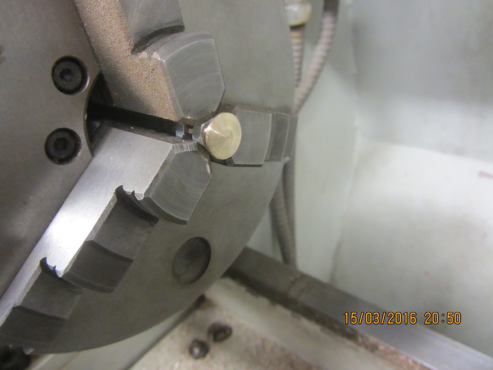

Step 5)
Turning the compound rest to an angle of approximately 5 degrees.


This is the "normal" position of the compound rest.


Step 6)
Parting the screw using the feed of the compound rest to form a slightly cone shaped head.


Making a saw nut follows the same principles. But the thread is internal.

Using a parting tool to remove the transition.

Screws and nuts as they look after parting. 
The small piece on top is cut off with pliers and filed smooth.

A screw is mounted in the chuck using two regular nuts to protect the thread. The head is sanded using grit 280 emery cloth. 

The nuts first receive a slot made by a hack saw. I mount them on a regular screw with the same thread before clamping the regular screw in the vice. After the slot is made, the regular screw is installed in the chuck of the lathe, and the head of the nut is sanded the same way as the screw.


Tuesday, March 15, 2016

Dovetail saw with copper back, children's size

Sunday I had the opportunity to spend some time in the workshop, and I managed to finish the handle, mount the back on the plate, produce some saw nuts and assemble the saw.
After the test assembly I disassembled it again to varnish the handle.

At some point I decided that the back was too tall for a child's saw, due to the weight of it that is. The raw back weighed 385 gram, so I was afraid that the saw might feel to heavy to be comfortable.
Therefore I removed roughly 1/4" from the lower part of the back. Making the new height of it approximately 9/16". In addition to removing weight, it also made the proportions a bit prettier in my opinion given that the saw plate itself is 2.25" high.

The handle was shaped using mostly a round file, and after I was pleased with the overall shape, I used sand paper starting with a grit 60 and ending with a grit 280.
I had never expected the handle to turn out as well as it did. But a lot of time with sandpaper really helps. also I am not used to making things that are this highly figured, but once I overcame my reluctance to start it, it was quite liberating not having to worry about square corners and parallel surfaces. It just had to be comfortable to grip.

The saw nuts were tuned on the lathe from some brass stock. The thread is M5, in order to make them fit a small handle.
I am fairly skilled at using a metal lathe, so turning something like this doesn't take very long. I didn't time myself, but I estimate that it took maximum 10 minutes for a screw and a bit less for a nut.
I filed a square on the screws and sawed a slot in the head of the screws. The slot is a bit too narrow to fit a usual screwdriver that wide, but since it is made using a hacksaw, the back side of a hacksaw blade is a perfect size.

Since I had removed the lower part of the back it did  no longer grip the blade sufficiently tight, so I took it back to the press to compress it a bit again. I figured that it was the most clever thing to do before I started removing the tool marks.
Those were removed by using a couple of files and some emery cloth / sand paper. To be able to work on the sides of the back, I made a small arrangement similar to that used for planing mouldings.
Two flat sticks were mounted horizontally in the vice, with the aft stick protruding 1/4" above the front stick. I then screwed in a small screw to act as a "planing stop". So the back could now lie on its side supported by the aft stick and the planing stop screw at the end.

Finally I found found some old varnish, very nearly dried up. I removed the dry layer and added some paint thinner. I used a piece of an old rag to apply the varnish.
The handle was sanded lightly between each coat, and I think I gave it 5 coats in total.

Now it just need to be used by some child in the workshop.


Children's dovetail saw with copper back.

Plywood handle.

Sawing the handle.

Workholding for the back.


Homemade brass saw nuts.


Sunday, March 13, 2016

Backsaw with copper back 3, the saw plate

When I attended the ATC class at Dictum five years ago, Chris Schwarz told me that it was possible to make a backsaw using the steel from a plaster scraper, if a person just wanted to try making his own saw, and do it in a cheap way.
I found a shop in the port where we are at now, that has cheap tools. So I walked there the other day and bought myself two 10" scrapers at around 10$ a piece. 

Normally I dislike destroying usable tools, but I decided that this destruction would serve a higher purpose.

I didn't want to accidentally bend the steel plate, so I decided not to bash the handle with a hammer to loosen it. 

After a bit of experimentation, I decided that the easiest way to remove the future saw plate from the scraper was to first split the upper part of the scraper where the two halves met. I think the two handle parts were cast separately and pressed together later. There was a clear joint that was easily split using  hobby knife.
With the plate mounted in the vice, I used a heat gun to soften the plastic on both sides.
As soon as the plastic softened, I pulled the two halves from each other. That made the upper part of the plate accessible.
A bit more heating and I cut through all the plastic that was in the holes of the plate.

I didn't time myself, but I think the process of removing the plate could be done in 10 minutes, if you don't try to experiment with other removal methods first.

The plate itself is 0.5 mm thick (0.02"), and on the plastic handle it said "Made in Sweden", so I guess that the steel is also Swedish. There is a very slight cupping along the length of the steel suggesting that it came from a roll. But it is easily within the capabilities of the back to keep it straight.

I used a tool bit from the lathe to scribe a line on the plate, so I could cut off the holes in the top. A small file or a permanent marker could have done the same. A pair of metal shears easily cut the thin plate.

The dovetail saw I have at home has got 20 TPI, but I didn't think I could manage to file that fine a set on my first attempt. So I settled for something a bit easier: 18 TPI.

I printed out a diagram, but it was 7% too small, so instead I wanted to use a trick advocated by Pedder from Two Lawyers Toolworks. The trick is that if you are going to make very fine teeth, you can use the blade from a hacksaw with the same toothing as a guide.

After about a third of the saw plate, I decided that it didn't work very well for me. Probably due to a crappy work station. I couldn't stand in a decent way with the file, and the whole idea of a narrow saw vice was somewhat destroyed by the way I had fixed the plate.
I took a quick decision and removed the hacksaw blade - and made the rest of the teeth freehand.
In hindsight I should probably have read up on how successful people file a set of teeth, but I never bothered.
My approach was to file every other tooth, and then reverse the plate and file the remaining teeth. It doesn't look too pretty, but the saw works which is the main thing. I'm sure the correct tools will help quite a bit, but it can be done without them as well.
My file was a triangular needle file, without a handle, so I ended up wrapping some tape on it to protect my palm a bit.
At first I just made an indication of where each tooth should go, then followed up with a second stroke to form it.

Raw material for a backsaw.

Splitting the handle.

Heat and a hobby knife gets the plate out.

This is what it looks like.

Nice looking Swedish spring steel (presumably). 

Start of filing the teeth.

These were filed freehand.

Half the teeth done. The other half started.


Saturday, March 12, 2016

Backsaw with copper back 2, making a handle.

There are a couple of wood species that are fairly classic for saw handles. Apple, elm, beech etc. But given my limited sources of wood out here, I had the choice between spruce or plywood. Technically I have a small piece of oak too, but it is too narrow to make a handle of, so that isn't really an option anyway.

So I opted for the plywood. I guess it is some sort of birch but I'm not sure. The thickness is 28 mm, or 1" 1/8. That is way too thick for a saw handle for a child, but removing a layer or two shouldn't be too hard.

Two Guys in a Garage has got a really nice page with loads of scanned handles. I decided that the Kenyon dovetail saw model looked nice.
If I lived in the USA, I would seriously consider buying a folded back and a saw plate from those two guys. Their prices seem more than reasonable,. And from what I can see on their home page, the backs look fabulous. (I am not affiliated with TGiaG in any way etc. etc.)

The only problem with the handle scans are that I can't figure out how to print them in the correct size. I tried various settings, but I still couldn't get it right.. I'm better at woodworking than setting up a printer..
So the handle ended up being 7% smaller than the original, but again since it will be a children's saw, that's just fine. Plus it saves me from the trouble of having to reduce the size.

The plywood is the same that is used for table tops out here, and it is sandwiched between two fat pieces of grain imitating plastic laminate. To mark out the outline of the handle, I taped the print out onto the plywood, and used one leg of a divider as an awl (I haven't got an awl out here). When I had made dots all the way around the handle and also marked the centers for the holes to be drilled, I removed the paper and headed for the pillar drill.

Someone has once purchased a 26 mm drill a bit similar to a Forstner bit. That was perfect for the larger holes on the print out.
The holes for the saw nuts, I only drilled with a 3 mm (1/8") drill, so I can use them later on for exactly marking the saw plate.
One of the large holes was a size of which I didn't have a drill, so I just used the 3 mm drill and made a series of holes next to each other following the curve.

I used a hack saw to saw as close as I felt comfortable to the dots. By doing that I ended up having a coarse shaped fat handle.

The next task will be to reduce the thickness of the handle and refine the shape.

Handleshaped plywood.

Thanks to TGiaG for provinding scans.

End view of the plywood.

Thursday, March 10, 2016

Backsaw with copper back.

I haven't been able to muster any energy for starting the shoe shine box, so instead I have undertaken a different project: A homemade backsaw.

Leif Hansson of Norsewoodsmith has wrote an excellent series of posts regarding how to make a backsaw.
I have used some of that information for inspiration, and I hope I will be able to make a usable saw shaped tool.

We have on board a large plate of 3 mm copper (1/8"). While I know that copper isn't a super traditional material for backs, the esteemed Badaxe toolworks actually make a saw with the back made out of copper. I would have preferred brass, as I like the shiny gold look of it, but copper should be able to do the trick too.

For once there is a slight advantage to working out here compared to at home in my own workshop. Because we happen to have a small hydraulic press, that can be used for bending saw backs.

In order to make my backs, I first sawed out a strip of copper from the plate. I chose to make the strip 4 cm wide (1" 9/16) Because that would give a back of around 3/4" height when folded.
After the sawing, I lightly chamfered the edges to remove any burr. I also scratched a line down the middle to help me determine where to start the folding.

For the first part of the bending, I placed the strip inside the V of a piece of anglebar that I had placed on the supporting blocks for the press. I then pressed a smaller piece of angle bar onto it, and thus formed a V shape from the strip. The small angle bar bent a bit, so for the next back I used a piece of 2" flat bar instead. That actually worked better.

The V shape was further bent by gradually pressing the sides closer to one another.
Once I was past a 90 degree angle, I placed the entire back between the support blocks, and stepped on the hydraulic press with all my weight. That was resulted in the pressure delivering its full potential - 15 ton.

I flipped the back over and gave it the same treatment from the other side, and finally I placed the upper support block something like 1/4" from the rounded side of the back, and pressed again. This resulted in the two sides touching each other nicely.

There are definitely some tool marks left on the copper from the folding, but since the material is so thick, I can easily remove them using a file, and still not compromise the stiffness of the back.
Also the sides didn't end up being exactly the same on each side, so the backs will require a bit of filing to look really nice.

Each of the backs I made are 10.5" long, not because of any calculations, but due to the fact that the copper plate had a section that would allow that specific length. I think they might be long enough for a 12" blade, since the handle also offers some support for the rearmost end of the blade.

My plan is to make a set of 10" saws with small handles that my boys can use in the workshop. One filed with rip teeth, and the other with crosscut teeth.

Ripping out a copper strip for a back.

Scratching a line in the middle.

Initial bending using angle iron.

Still a bit of way to go.

The final and nicest looking back is for Brian Eve.

Teardrop shape.

Wednesday, March 9, 2016

A small barn for the summer house 3, approval and ideas for raising

While I was at home last period, I took my drawings down to the planning department at the town hall.

I had scrutinized the requirements laid out in the plan for that specific area, but I was still a bit uncertain about the outcome.

I talked to the same person that I had previously discussed the case with, and I showed her my drawings.
After looking at the drawings a bit she said that it was fine, but she still needed one drawing, that would show where the shed was going to be placed on the lot. If I made a drawing that would do that, I could just submit the application online and start building.

She even commented that my drawings were of a higher quality than they usually saw. That made me glad, because I had honestly considered if it was of little use to make such elaborate drawings, if a simpler sketch would do. But maybe that helped showing that I was serious about the build. Anyway, I just have to decide where to build the shed, and then make a drawing that will show it.

With this major "obstacle" seeming ly out of the way, I have given quite a lot of thought to the raising process.

The overall plan is to build in some steps.
As a start I am going to make the lower frame complete with all the required joints, including the joists.
Once those parts are ready, they will be taken to the summer house.
Next I am going to dig some holes for all the concrete posts that will be cast.
The lower frame will then be assembled in position over the holes and leveled out at the intended height.
Then I am going to mount the casting brackets on the frame and pour the concrete. That should ensure a level topside of the lower frame.

Once that part of the project is out of the way, I can proceed with making the rest of the joints while the concrete will have ample time to set,

The next major step will be to assemble the bents and try to raise them. I am going to use chain blocks and poles etc.
Once the first bent is raised, it can be used for raising the following bents.

In my imagination the upper plates and the rafters will merely be a walk in the part. I am afraid that reality might look a bit different once I get to that actual part of the build.
But sitting out here and doing the raising by doing sketches of the individual steps using pen and paper makes it look easy, and that is a lot more comfortable than imagining all the steps that could go wrong. I'll probably discover those when I get to them.

Sunday, March 6, 2016

J. Siegley smoothing plane No 3

Even though my birthday is some time in the future, my older brother has already purchased a gift for me.
I have to admit that I helped him in the direction of the present, but that doesn't detract a bit.

I had spotted an old plane on a classified page in Denmark. It just said: Plane, J. Siegley and there was a picture of the plane and the accompanying box.

The vendor lives in the same neighborhood as my older brother, so I asked if he could pick it up for me. He readily agreed and offered that I could get for my birthday, which was fine with me.

Today my brother got hold of the plane, and sent me some pictures of it. Based on the Stanley size system, it is a No 3.

I have tried to search the Internet for information on the Siegley planes, but there is not quite as much information as I had hoped for, so if anyone reading this could provide any information, it will be greatly appreciated.

As far as I read, the Siegley company was purchased by Stanley in 1905. From 1905 to 1920 Stanley manufactured the Siegley planes alongside their own.

But I think this plane is older than the Stanley era due to the fact that it only says J.Siegley on the blade. There is no mention of Stanley anywhere on the plane.

There is no lateral adjustment feature on the plane.
On Stanley planes they were introduced in 1885 (according to the unsurpassed wisdom found at Patrick Leach's blood and gore page) but I don't know if Siegley never had a lateral adjustment until they were purchased by Stanley?

My older brother took that plane apart and took some pictures of it. It was well oiled and doesn't seem to be rusty. the fact that someone made a designated box for it makes me believe that whomever the owner was, he took care of this plane.
The rear tote is a bit loose, but I guess it can be tightened up.

My guess is that it would make a fine restoration project to carry out on board..


J. Siegley plane No3


J. Siegley blade

No lateral adjustment on this plane.


Plane transport box