Sunday, May 27, 2018

A new door for the quick closing valves cabinet 2, door and varnishing.

My less than ideal resawing meant that there was a lot of material that needed to be removed by a plane before the four pieces of wood were flat and reasonably identical.

First a rabbet was planed for receiving the glass (which is not real glass by the way), and next a small beading was planed on the front side.

The door frame was assembled with short tenons (1.25" long), and the beading was made continuous by mitering the corners of the beading /rabbet portion of the parts.

I removed the glass form the old door and adjusted its size so it would fit the new door.
The glass was mounted by means of some Sikaflex and 12 small screws that were driven in at an angle, so the head would press the glass down into the rabbet. Not exactly high end furniture style, but OK for this application.
A bit of the Siaflex oozed out, but given that the glass is plastic, I don't want to risk destroying it by being too eager with a chisel when scraping it off.

The two door latches were then mounted by chiseling out a recess, so I could attach the nut from the backside. They are not designed to be used on stuff much thicker than 1/4", so I had to remove some material from the front and the back.

Finally the door was mounted using the reclaimed hinges, and the door latches were adjusted so they could keep the door closed.

I have applied one coat of varnish to the door and the face frame, and as soon as it has dried, I plan to give it another coat, I think that will be sufficient, though the common rule of thumb according to boat varnishing in Denmark states that you should apply 7 layers of varnish with a light sanding in between. This is probably a rule of thumb that has been invented by the manufacturers of varnish!


New door, with first coat of varnish.

New door prior to varnishing.

Short tenons 

Beading detail (and ugly mark from the clamp)

Face frame mounted.

Latch for the door.


Thursday, May 24, 2018

A new door for the quick closing valves cabinet 1, hinges and face frame.

Fire protection has generally always been a big issue on board ships. There are various systems in place for keeping the ship and crew safe. Among those systems are fixed fire fighting installations such as either Carbon Dioxide total flooding plants, Flexi fog water mist extinguishing systems, regular sprinkling systems etc.
A system which is not in use int he merchant marine anymore is the use of halon. It was a fine system, but it was ruled out a couple of years ago due to the fact that halon gasses were very effective in depleting the ozone layer.

Other types of protection might not be so obvious, but one of those is something called quick closing valves.
These are spring loaded valves that are fitted to oil tanks (fuel and lubricants), and in regular service they are kept open. In the case of a fire in that area of the ship, or on that particular system, a cabinet for activating those valves are positioned outside the accommodation. That way you can stop the flow of oil in case of a fire and do it from a safe distance.

For some strange reason, many of these cabinets rust like crazy. It is probably because the cabinet itself was never really intended to be mounted outside on a ship, and a stainless steel cabinet is more expensive than a cheap non stainless cabinet is.
Even a coat of paint is normally not enough to keep them good looking.
Fitting a new cabinet instead of the old is a huge and complicated task, mainly due to the fact that you would have to disassemble the actual system in order to move it into a new cabinet, and by doing this you are deactivating a safety system, which is not something that is taken lightly.

On our cabinet, the cabinet itself is in decent condition, but the door has rusted through, and it looks bad.

We discussed the possibility of making a new door out of wood, and mounting that on the cabinet, so it would look a bit better. And I was happy to give it a try. The actual function of the cabinet won't be changed.

The first task was to find a set of hinges. The original hinges on the cabinet are some that are an integral part of the rusted door, so I couldn't really use those. On at least two of my former ships, I knew exactly where there were some spare hinges,but that really doesn't help me on this ship. Out here we haven't got any. So I tried searching the vessel to see if I could come up with something. One of the deckhands told me that he had seen part of an old metal box that had been scrapped lying in the garbage collecting room. I had a look and fortunately it was the top side of the box, complete with a set of hinges that had been welded on during construction of the box.
I brought the parts with me to the workshop and removed the hinges using an angle grinder.

The wood was less of a problem. We have a decent stash of wood on board, including some 2x4 exotic looking reddish wood. (I have no clue what it is, but it seems hard and durable).
I had a bit of help digging the plank out from underneath a bunch of other planks, and cut two pieces of to use for the door.

We happen to have a nice Festool circular saw on board, so I decided to use that one for resawing and ripping instead of doing it by hand. It was a lot faster, but the results were not nearly as accurate. Part of that problem is probably that someone has thrown away the fence for the saw. I have no idea why anyone would do that, the saw itself comes in one of those large plastic boxes (Systainer I think) so there was plenty of room for a fence in there.
So I had to do my sawing freehand following a line.
I did it on the open deck do avoid getting dust all over the shop.

At first I made a face frame. This will be screwed to the front of the cabinet, and then the door will be mounted on it once I get that far in the project.

Salvaging a hinge using an angle grinder.

The top part of an old metal box.

Crappy re-sawing results

Face frame glued up.

Rusted door of quick closing valves cabinet.
(I had to use flash, hence the worse than normal quality)


Tuesday, May 22, 2018

Smith & Wesson 629 presentation case 8, project completed.

The remaining part of the felt lining was installed and after letting the glue dry for a day, I used a sharp and pointed knife to cut away the felt covering the 50 holes for the individual pieces of ammunition.

The hinges were mounted and so were the latches for keeping the box closed.

Finally I chiseled MMXVIII in the underside of the box marking the completion of the project.

After taking some pictures, I handed the box over to my friend, and he said that he would send me some pictures with the revolver and the ammunition loaded in the box. But off course this will only be after we sign off.


Thoughts about the build:

I like making small box like projects, and this one had a nice manageable size. It ended up being 8" x 16" x 3".
There isn't much wood in a project like this, and the size of the parts make it fairly easy to process out here.

At first I was a bit skeptical to the dovetail lay out, I was afraid that it might look weird. But I am glad that I went along with it, because I actually think that it looks fine. And I especially like the way I managed to split the lid and the base so that after trimming, the divided pin that is very close to the other pins in size.

My experimental finishing is probably the biggest success in this build. The surface feels very smooth, but it is not super shiny. And I really like the look of it.

Mounting the felt lining was a bit harder compared to other projects I have done, due to the partitions in the base of the box. Cutting the holes for the ammunition block felt luckily went as planned, though it took quite some time to carefully nibble away with a really sharp knife.

The latches worked and looked better than I had expected. They are not cast, but made out of some thin stamped brass that has been given a surface treatment to look old. Originally thought that they looked kind of flimsy, but I am glad that I chose those since I think they look very fitting.

I haven't timed the build, but an estimate is that I have roughly 25 hours in it. It isn't a very fast build, but the stock preparation takes a lot of time when you have to do the resawing by hand.

All in all I think this is one of my better builds, and I am even a bit envious that I can't bring the box home with me. I guess that is a fine indication that the project hasn't been a complete disaster.

Smith & Wesson 629 presentation case opened.

Two latches for closing.

Close up of front corner.

Ammunition block lower left corner.

Close up of felt termination in angled groove.

Box before cutting 50 holes and mounting hinges and latches.


Friday, May 18, 2018

Smith & Wesson 629 presentation case 7, felt lining.

Yesterday I gave the outside another coat of marine varnish, which I again applied using some steel wool.
I lightly wiped off the excess, and today the surface looked fine and dry.
The surface was not perfect, and I decided that I preferred a slightly more matte look.
So once again I smoothed the surface using the steel wool, and I really like the look of the surface after this treatment. There is still a bit of gloss in the pores of the wood, but the surface is as smooth as a nuns stomach (as my dad would say).

The felt lining is not especially complicated in theory. You measure and cut the size you need. But in real life it is a bit harder than that. suddenly the fabric stretches and when you try to carefully remove a bit, suddenly it was too much and you need to start over again. It can also be an advantage if you start out a fraction too short, then the stretch can save you.

I am using regular white glue for the fastening of the felt, because it is what I have, and it works OK.

The angled groove that I made after has shown to be a very effective way of terminating the felt lining. It gives a very clean look in my opinion, so I will definitely use that next time I am going to make a similar type of box.

Lined lid.

Glue smeared on the ammunition block.


Wednesday, May 16, 2018

Smith & Wesson 629 presentation case 6, ammunition block and surface treatment.

The ammunition block was ripped close to its final size, and then I planed one of the sides to act as a reference.
I crosscut it to the correct length, and planed the remaining side and the bottom and top of it, testing for a nice fit in the base.

I removed the block again and marked up the locations of the 50 holes for the individual rounds of ammunition.
The location of each of the holes received a small mark made by an awl before being drilled.
While my work holding and worktable etc aren't very good out here, the same thing can not be said about our drill press. It is a "Strands of Sweden", it is similar to Lie Nielsen in hand planes when it comes to drilling machines. It is really accurate and a joy to use. It is actually a stark contrast to the crappy drill press I have at home.

I drilled the 1/2" holes all the way through the block. The bottom of the base will work as a stop, so by doing it this way, I won't have to worry about getting all the holes to the same depth.
Two of the holes turned out less than perfect, the first one was because i didn't hold the piece firmly enough when retracting the drill, so it caught the side and made the hole oval.
The second hole was due to a heavy roll of the ship that caused everything to move. In retrospect I suppose that I should have waited with the drilling until some day with calm weather, but it was just a single time the ship moved that much.

After sanding the surfaces lightly, the ammunition block was finally glued in place.

While the glue dried, I took a cup of tea.

The dust seal wasn't completely level at all corners, so I gave it a few swipes with the plane and rounded the top again with some sandpaper.

At this point even I couldn't ignore the fact any loner, that the time for sanding the outside a bit more was getting awfully close.
I grabbed the sanding block and gave it a good workout on the outside using some grit 80 that we happened to have on board.
All the remaining pencil marks were removed and it started to look really nice. I found some fine emery cloth next. I think that it might be something like a grit 180 or 240, but I am not sure - it wa finer than the 80 which was the important thing.
Another round of that and the box looked downright fine.

The next step ought to be fitting the hardware, but since this is a ship and there is sometimes a lot of grime and oil etc in the workshop, I chose to give the box a coat of varnish instead. This will hopefully protect the surface a bit from grease stains etc.

I don't have any abrasive pads on this ship, but I found an old roll of steel wool. It isn't particularly fine, so I guess it is grade 0.
I poured a bit of varnish into a paper cup and dipped the steel wool into it. It rubbed the varnish into the surface using the steel wool, and once I was done, I grabbed a clean rag and wiped of the entire surface.
So far it looks good, but I am anxious to see what it looks like when the varnish has dried.


Interior of the box.

Bottom finished.

Top finished.


Tuesday, May 15, 2018

Smith & Wesson 629 presentation case 5, dividing the interior.

The remaining part of the dust seal was glue in place, and while the glue dried, I started on the divider for the interior of the box.

It was made of a similar strip as the dust seal, but it was reduced to 1.5" in height (38 mm), this was also the height of the angled groove above the bottom.

The divider had its top rounded, and I started measuring from my 1:1 scale drawing, to transfer the measurements to the box itself.

A fine thing about adding a layer of felt later on is that you don't have to worry about markings etc. And the interior finish can also be left a bit more coarse.
I chiseled a small dado where the divider would meet the dust seal, so that the end of the divider had some support.
Since the divider is fairly thin, sort of 1/4", I was not sure if it could stand up to the load if it was merely glued together with a butt joint. So I took the extra time and dovetailed the pieces together with a mitered top. I marked the dovetails out by hand and surprisingly they went along really fine. at least the two that were right angle joints did.
The angled joint wasn't very impressive, but it will still hold up better than a butt joint, and in the end it will all be covered with felt.

The completed divider was glued to the bottom of the case, and the ends were glued into the dadoes that I had made.

With that part out of the way, I started on gluing up a block of wood that will receive 50 holes for holding the ammunition to the revolver.


Divided interior, dust seal and lid

First part of the divider.

Eyeballed mitered dovetails.

Gluing the divider in its place.

Sunday, May 13, 2018

Smith & Wesson 629 presentation case 4, Splitting the box and making a dust seal.

With the box dry, I first planed the protruding parts of pins and tails and sanded lightly.
I then marked the division line on the remaining two sides. I had marked it out on the ends in connection with the initial marking of the tails.

I have designed the split so that I only needed to remove 3 mm of wood (1/8"). The saw kerf is not that wide, so I tried to saw between the lines and then used a plane for cleaning up the joint.

Once opened, I was pleasantly surprised to find that there was very little glue squeeze out on the inside. I used a chisel to remove the little there was.
I planed the mating surfaces of the lid and the base and followed up with a bit of sanding, I was curious if there were any internal stress in the boards, but everything stayed flat and square.

The next step was to make the interior fittings. These consists of some flat strips of wood that are going to be glued to the inside of the base in a way so that they will extend a bit into the lid, acting as a dust seal. There is also going to be some lower strips that will form the division that will create the space for the revolver. Finally there will be a piece of board that will hold 50 rounds of ammunition.

I have seen on a forum where someone discussed decorative presentation cases, that one method of making those dust seal strips includes an angled groove that will sort of conceal the end of the fabric used to line the box with. In my case green felt.

The first task was to plane the strips flat and to the same thickness. With that complete, I clamped them together and made them all the same width.
I marked the inside height of the base on the strips, and planed the top part of them at an angle, with a rounding at the top. That was to become the dust seal, and the reason for the angle is to make it possible to open and close the lid.

I marked out the position of the angled groove, so that it would be at the same height as the base itself without the dust seal. and made it using the combination plane. I just held it at an angle and took a couple of passes.

The strips were then sawed to the correct length aiming at a 45 degree miter in the corner. I suck at sawing miters, so there is a bit of a gap. My hope is that anyone who will look into the box will be so impressed with the revolver inside, that they won't notice those small gaps.
I glued on three of them before calling it a day (night actually).

Sawing the box in two.

The dust seal strips with the angled groove visible on the off cut.


Saturday, May 12, 2018

Smith & Wesson 629 presentation case 3, dovetails and assembly.

Laying out dovetails is normally fairly straight forward, but I had to think hard on this set, because of the plan to glue up all at once, and then split the box to form the lid and the base.

I had to incorporate two grooves, and I also wanted the split pin to be the correct size after splitting and planing.
In the end I managed to make a layout that suited me. I also need to take into account that my narrowest chisel is 1/4".
So I can't make those ultra thin pins even if they would look fine on a project like this.
I made a template for laying out the angles of the dovetails, and I settled on 1:8 sine it is hardwood.

Before dovetailing, I did something unusual (to me at least). I used by shooting board to trim the ends to the become square and the pieces to become the exact same length.
I felt that I had to use this approach, since the stock is thin, so I couldn't just plane away to remove inaccuracies later on as I normally do out here.

Since the pieces were comparatively small, I was able to do it tails first, which I prefer. The actual chopping out was done on a piece of wood held in the vice, and then with the work piece clamped on top of that.

Once all the dovetails were completed, and I had dry assembled the case, I made the rabbets on the lid and bottom, to make them fit in the grooves.
I have never had much success with the small nicker when going across the grain, so I tried instead to first score a line with a hobby knife.
Then after every two passes or so with the plane, I would score another line to keep the rabbet looking good. It took a bit longer than if I had just planed the rabbet, but it looked so much better, so it was definitely worth it.

The rabbet along the grain was a walk in the park. A sharp iron does the trick.

Based on Sylvains comment to the last blog post, where he asked if it was possible to change the fence to the other side, I had decided that I could try to make a new set of rods that would allow me to do just that.
The engineer apprentice on board will soon attend his exam, and he needed a bit more routine in using a lathe. So I made a drawing of some rods that would work, even if we didn't have the correct tap and die for making the same thread as what is originally in the plane.
He made two parts, and I made the remaining two, so I could use the plane tonight.
It is not a 100% elegant solution to use the plane the other way, but it works, and the is the most important thing.

So after making the extra set of rods, I planed the rabbet that would have been against the grain, but now wasn't anymore. It worked brilliantly.

Again I made a dry assembly, this time incorporating the two panels. One of the panels needed to have one side trimmed with a single swipe of a plane, to make it slide easier in the groove.

The edges between the rabbets and the top were rounded to soften the look.

Glued up box.

Shooting the ends.
 
Workholding for chopping out dovetails.

Record No 50 with fence on the "wrong" side

View from underneath. The wooden fence was needed so I could plane with less than the full width of the iron. The depth stop is a fence (I can't remember for what use) that has been flipped 180 degree

Dry assembly of the box.


Wednesday, May 9, 2018

Smith & Wesson 629 presentation case 2, getting groovy

The build continued today with a bit of work on the sides and and ends of the presentation case.

First I straightened one side of all pieces, and then I marked out for the final height of the box.
I ripped the pieces slightly over sized, so I could plane them to the final dimension. I made sure to keep an eye out for grain orientation which helped a lot.

I marked the individual pieces with some carpenter's triangles, and again I made sure to keep an eye out for grain direction , since I had to make some grooves on the inside of all the pieces.

After looking at the top and bottom, I decided to use the 1/4" grooving iron. It was the same one that I had sharpened last time I was on board, so I knew that it would work.
The iron was installed in the combination plane, and I made a few test swipes on a piece of scrap, to check if was adjusted OK. It might have been sheer luck, or it could be that I I am slowly getting better at setting up the plane - but anyhow the plane took a nice crisp shaving right from the start.

For the first grooves the workholding wasn't a big deal. I clamped a large piece of wood in the vise, and used some clamps to hold the pieces onto that large stick.

The challenge came when I had to make the set of grooves destined to receive the bottom of the case.
I couldn't turn the pieces around and plane from the other end unless I wanted to effectively ruin it all with tear out.
So after a few experiments I made some sort of a sticker board, and planed the bottom grooves from the same side.
I managed to make some really nice and crisp grooves on all pieces, and there was practically no tear out. It is nice to see that a little forward thinking on grain direction actually can help.

The next step will be to cut the sides and ends to their final length and shoot the ends of those pieces, when that is done I am going to lay out some dovetails.

Planing all pieces to the same height.

Workholding for the bottom grooves.

Sides and ends with grooves.

Tuesday, May 8, 2018

Smith & Wesson 629 presentation case 1, stock preparations and ideas

One of my colleagues has got a S&W 629. He is Norwegian, and apparently it is a bit easier to be a gun collector and user in Norway compared to Denmark.

When I built the pilot ladder cabinet, it once again stuck me that I like building boxes of different types, so I had decided that this time the project had to be a box of some sort.

Most of the time out here I just build something and never really bother about if it is needed or wanted by anybody, but I eyed an opportunity, to make something that would fill a need and be appreciated at the same time, so I asked if he would be interested in me making a presentation case for his revolver.

He was thrilled that I would do that, and I was equally thrilled to have a goal to work towards.

He told me a bit about the gun and had some of his acquaintances take some pictures of a similar model, so I could get a couple of overall measurements.
He would like if possible, that there was room for some ammunition in the box as well, so I have tried to plan ahead for that as well.

He has been on this particular ship for a long period, so he has a special relationship to it. I decided that to honor that, I would use the remaining parts of the pilot ladder as material.

The overall dimensions of the presentation case will be approximately  16" x 8" and 3" tall.
That should give the interior space that I am looking for.

I plan to dovetail the box together, and install floating panels as top and bottom at the same time. Then after the glue has dried I am going to saw the box apart to form the lid and the base. That way I should be fairly sure that the parts will fit together, and the grain will be matching.

The inside will have some sort of partition to define where the revolver will be placed, and it will be lined with felt to make it look nice.

Stock preparation is (as usual out here) a matter of re sawing some old pilot ladder steps, gluing up a couple of panels and planing the boards and panels.

Re sawing a step from the old pilot ladder.

Boards and panels ready.

Monday, May 7, 2018

Investing in the future.

Wow, that title sounds a bit pompous and self righteous..

About a year ago I wrote a post about an idea I had: to make some ready to assemble kits of small ships for the local kindergarten.

I finally got my act together and moved a lot of the scraps from the barn at the summer house back home.

With the Barnsley table complete, I just had time to tackle this small project prior to returning to sea.

The overall design of the ships is inspired by ferries of the 1950'ies-1960'ies. Back when masts were still used for holding the radio antennas and technically also for the booms for cargo handling.

I removed the tongue from the boards and split them to make some 6 cm (2.375") wide strips.
These would form the hull.
All of those were sawed to the same length of 27 cm (10.75").
I made a jig to enable me to make a cut for the bow that would result in something like a 60 degrees angle (eyeballed). It looks better to me than just having two 45 degrees bow portions meet.

A bunch of superstructures were made next. 4 cm (1.6") wide and 11 cm (4.375") long.

I purchased a broom stick and made a run of funnels from that one. Each funnel 2.8 cm (1.125") long.

After thinking a bit, I came to the conclusion, that it was easier for me to buy all the stuff that was needed for the project instead of giving more jobs to the adults at the kindergarten. So I went to the lumberyard and purchased  a box of nails that would be appropriate for the thickness of the wood, and some long pieces of pine dowels  all 8 mm thick (5/16").
All the masts were sawed of at a length of 12 cm (4,75")

I clamped on some pieces of scrap to the table of the drilling machine to work as a jig for boring multiple holes in the same position. Holes were drilled in the hull for the masts, and in the superstructure and the funnel to act as pilot holes for nails.

I didn't sand the pieces since I figured that it would be something the kids could do themselves, and it would give them a greater sense of ownership in the process.

All parts were neatly packed in a small cardboard box, a small roll of sand paper, a handful of nails were put in a small plastic bag and finally a quart filled glue bottle was put in the box with it all.

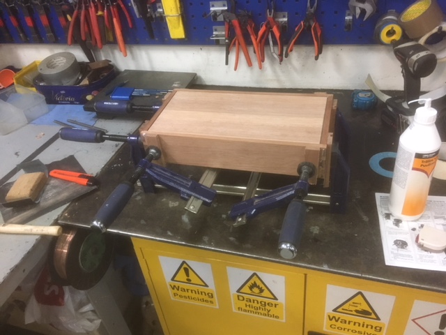
I assembled one ship out of a damaged hull piece, so that they could use it as a template.
The ship is made out of 5 pieces of wood and uses 3 nails, so it is not the most complicated build that I have ever made.
A total of 36 kits were handed over to the kindergarten, and I asked how many kids they had, so I could have made a couple of more if needed, but they assured me that it was fine.
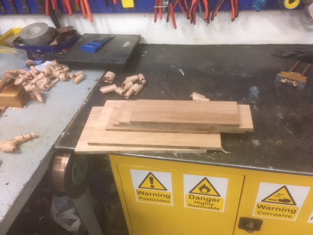
The remaining pieces of scrap were turned into lengths of strips with various sizes, so that they could make something else from their own design later on.

Regarding the title of this post, I have invested a bit of time, say maybe 2 hours of efficient work in making the kits. The scrap wood would most likely have ended up as fire wood so despite that it originally had a cost, I value it to zero.
the broom stick was 4$, the three long dowels (each 14' long) were a total of 12$.
The package of nails was 9$, so a handful of that is maybe 2$.
Sandpaper and the remains of my old glue bottle is maybe another 5$.
A grand total of 32$, (equivalent to the price of one and a half beer at a Norwegian airport) plus some hours of work was what it cost me.
My hope is that perhaps one day in the future one of those kids will remember that making things out of wood was fun, and will take up woodworking as a hobby. Or perhaps they will bring the ship home with them and show it to their parents, and someone will try to make something similar on their own.

When Gustav was in kindergarten, I helped them one day by casting hammers of Thor (Mjølner) out of molten tin. Approximately half a year ago, Gustav told me that a girl in his class remembered casting those 11 years ago when they were 4 years old. So I reckon that if you can make something a success when you are 4 years old, you might just remember it later on in life, and it might be the start of a good hobby.
Future investment ship template.

Lightly damaged port bow.

ripping the tongue from the board.

Bow making jig. 

The rest of the scrap wood turned into various sizes of strips


Sunday, May 6, 2018

A Barnsley hayrake table 4, final assembly.

The breadboard ends were sawed flush to the side of the tabletop, and the top was then flipped over so I could smooth the underside first.
Planing such a large glued up top of larch was something I attempted last time I build the table, and the results were not good at all. So this time I decided to start with what I knew would work: A portable belt sander and some 40 grit bands.

Once the underside was smooth and flat, I sanded the sides and ends and chamfered all the edges on that side with my small Japanese chamfer plane. I flipped the top over again, and the I made some buttons out of elm to attach the table top to the base with.

The tabletop was then mounted in the correct position, and I sanded the top side with grit 40, 60 and finally 80.
The edges on this side were chamfered too, and that as they say - was that.

I tried taking some glamour shots of the completed table, but my photographic skills are as you know not the best. Furthermore the table is so large that it is difficult for me to get a proper distance for taking good pictures without any disturbing things in the picture.

I have logged all the time that I have used on the table, and I was a bit surprised, that it took me longer to build than the first hayrake table a couple of years back. I think that the difference is that I made breadboard ends on this one, and also the classic way to attach the upper cross stretcher.
The time totaled at 49 hours and 10 minutes, efficient work time that is. If I had to go see why Bertha was barking, or to get a cup of tea, the clock was stopped.

Personally I think that this table looks a lot better than the first one, especially since the size of the top fits better to the base. And I also really like the look of the breadboard ends.

While it isn't of great importance how long time it takes to build something, I like to monitor it due to my own bad memory.
In case someone sees the table and thinks that it looks nice, and asks me if I could make one more, then I would like to remember just exactly how long time it took me, so I don't accidentally say that oh, I can make one of those in a long weekend in the shop.


Barnsley hayrake table, 10' x 4'

Longitudinal stretcher to crosspiece in hayrake.

Crosspiece to arms of hayrake.

Hayrake to legs.

Japanese edge nicer (chamfer plane)

2018 (plus sack of garbage behind stretcher)

Breadboard end.