Showing posts with label Lathe. Show all posts

Thursday, January 20, 2022

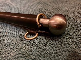
Marlinspike with a leather sheath

 I have helped a lot of my colleagues turning marlinspikes out here, and I have made some myself as well, but those have either been for the ship's bosun shop, or as gifts to other colleagues. I have however never made one for myself. 

Probably since I don't need a marlinspike, but this time I decided to make one for myself anyway.

I found an old steel bolt for the cylinder heads of the main engine, and I deemed that it would be perfect for the purpose.
The shape is the one I usually help the trainees to achieve, a long sleek body with a mushroom shaped head. The conical body gradually turns from round to oval the nearer to the tip of the tool it gets. the tip itself is ground or filed flat and gets and edge of approximately 60 degrees.

The dimensions for my marlinspike is a length just shy of  12", the head is 1.25" in diameter, the upper part of the body is 19/32" which tapers to a width of 1/4" at the very tip. Just above the ground part, the width is 3/8" and the thickness is 9/32" (due to the oval shape).

A hole was drilled in the upper part and I made a small D-ring of bronze that I silver soldered in place, this is so that the marlinspike can be secured with a lanyard when working aloft. I made an extra D-ring that I could mount on the sheath, so that the securing line has a place to be secured to.

For the sheath I decided to test myself a bit, and make it as small as possible.
A wedge shaped piece of leather was sewn to the backpiece. this would form a rabbet that the rounded part of the sheath could register to. 
During the sewing of the wedge, I mounted the D-ring on the sheath. The wedge also moves the marlinspike a bit forward of the back piece, so that it will in theory stay a bit more clear of the hip when worn in the belt.

The rounded part was first made wedge shaped, so that the sheath would also taper in its length, both in width and height. I sewed it on using angled stitches that would enter the side of the rounded piece and pierce through to the back of the leather. 

Finally the edges were trimmed and polished a bit.


Tuesday, March 16, 2021

Marlinspike manufacturing

It is not a secret that I like to turn stuff on a metal lathe. On my first voyage with the Lehmkuhl, I made a large marlinspike just to test out one special way of making cones. 
The marlinspike was well received by the deck department, and I ended up making a couple of smaller ones later on that year.

I have great difficulties saying NO to a Newfoundland dog and to young people wanting to learn from me. So when I signed on this time and almost all of our volunteers asked me if I would teach them how to make a marlinspike I replied that I'd be happy to.

Making a marlinspike is a fine little project. There are different processes that involves different tools, and you can leave the project for some time and pick it up again later without any issues.
The turning teaches people a basic understanding of the lathe and how to use it. The surface is improved by a file and by sandpaper before it is hardened.
Some sort of head or handle is dealt with next, and finally everything is polished using some fine emery paper. 
One of the volunteers asked if I could also help him make a sheath for the marlinspike, which I was happy to help him with. Soon after, a couple more of them wanted to do that too. Then one guy wanted to make a sheath for his knife to match the marlinspike sheath, and another one jumped on the same idea. So I have spent a great deal of time helping and instructing in leather work and metalwork this time.

An interesting thing was to see how they each had ideas as how they wanted the head/handle made. So each has his own very distinct marlinspike. 
So far we have made heads from leather, wood, laminated wood, copper & brass and steel.
Most of the marlinspikes have been around 10" long, so they work well as personal tools that can be brought with them into the rigging. A couple of them have been 13-14" and a bit beefier, intended to be used at the deck mainly for splicing wire.

A great thing about all the projects is that people have all been incredibly proud upon completion, and they have each succeeded in making a functioning tool that they can use for the rest of their career. And I am happy because I think that I may have planted a small seed of making in each and everyone of them.


Adrian's marlinspike

14" (as far as I remember)

Wood from various ships he has worked on

Laurids' and Simon's Marlinspikes

Laurids' sheath for the marlinspike

Simon has made a sheath for his pocket knife

Aske's sheaths

Brass & copper head

Nice work for someone new to leather working.


Saturday, May 25, 2019

Ash log Roubo project 4, leg vise spindles and chops.

During my final trip on the Troms Capella, I used the ships lathe to turn a tap for making wooden threads.
It makes a 2" thread with a pitch of 4.5 modules. Modules is actually just a fancy word for Pi mm, so the thread is 14 mm or pretty close to 9/16"

It seems as though I only took one picture while making the tap, and now it is at home, so I can't really take anymore pictures of it at the moment.

The tap worked really well, despite ash not being the easiest wood to turn a thread in.
After making the internal threads in the legs, I watched an episode of Roy Underhill, where he makes a die for wooden threads.
I basically copied all he did, and though I couldn't do it as fast as him, eventually I ended up with a die that could produce a thread.
The first spindle looked utterly magnificent, with the slight but important part - it didn't fit..
I had to do quite a bit of adjusting to get the die working in a way that produced a spindle that would work. But finally I had two spindles (made out of whitebeam).

I turned a couple of ends for the spindles out of some apple, and glued them on. Then a hole was drilled through, and a couple of sticks were turned and inserted.
Those sticks were retained using small ebony pegs, so technically I can't keep on claiming that the entire bench is made from the same tree.

The chops were made out of the ash log, and I made those a bit tapered to make them look nice.
A square recess was chopped in each of them to receive a garter for the spindle.

Completed spindle.

Close up of cutting action of the die.

Turning a spindle blank on the metal lathe.

Fabricating a 2"/4.5 module tap.

Two pieces of ash for the vise chops.
 
Recess for the garter.


Sunday, May 19, 2019

A fid for a friend

I am back on the ship, and this time our sailing schedule is to do evening cruises in and out of Bergen, so I have the rare pleasure of a functioning Internet connection that comes with being alongside in our home port.

Some might think that evening cruises are a bit dull, but just like all woodworking can't be ebony inlay, once in a while you need to build the casework that will house the inlay.

These cruises with paying guests are part of our bread and butter, and in addition to providing the ship's foundation with some needed cash to run the ship and keep her well maintained, these cruises actually give the residents of Bergen a sense of ownership of the Statsraad Lehmkuhl.
So it is part of our strategy to be active visible and accessible in our home port for two months of the summer every year. That way people feel proud of the ship and recognizes it and feels that it is "their ship."

The incredible support that we have from the local community can not be overestimated, so it is only fair that we do our part in giving back to the community by doing these small evening cruises.
And just like in woodwork, it is difficult to say that one operation is more important than the other.

Since there are comparatively few tall ships on a world wide basis, often young people who wants to work in this field have a difficult time finding a ship to do it on, we usually have 6-8 volunteers sailing with us, who have completed their basic training on a training ship.
One of these volunteers told me last time I was on board that his birthday was tomorrow, (we discussed it because it was close to the date where I was signing on again).
Now these volunteers get room and board and that is it, but they do an incredible job on board, so I thought that I would make him a small birthday gift.

So a week ago I took the time to head into the shop and I turned a fid for him. It is made out of some dark exotic wood that I once purchased, and I think it might be mahogany, though I am not sure.
Turning a fid was pretty straight forward, and in the end I tried to polish it with some Carnauba wax. I have never tried this before and I was so impressed with the look of the surface that I ended up making yet another fid for him. This time a bit smaller.
He doesn't read this blog, so it will be safe for me to post a picture of the large fid here. I forgot to take pictures of the smaller one.

The large fid has a length of almost 12", and the thickness at the fat end is something like 1.5"
I can't remember the size of the smaller one, and it is already gift wrapped.


Wednesday, October 24, 2018

Stanley # 20 compass plane locking screw.

We have a lathe on board, and just to make sure that I don't forget all about how to use one, I once in a while try to do a bit of turning on it.

I had one year of shop class prior to the engineering college, and I was actually quite skilled at using a lathe at that time. However that was 24 years ago.
The two most difficult things as far as I remember was turning correct fits for bearings, and to cut threads on the lathe. Not the type where you use a tap or a die, but grinding the tool bit and adjusting it all and then lead the lead screw take care of the pitch.

Searching for an appropriate challenge, I ended up reading about the Stanley # 20 compass planes. 
According to Patrick Leach's excellent pages on Stanley planes , the # 20 often has the original knurled locking screw replaced. So making a new one of those might be helpful to someone out there sitting with a recently acquired #20 missing that screw.

However excellent Leach's page is he doesn't reveal the thread of this screw, but I managed to find that information on a British tool forum.

The screw was apparently of the much under appreciated UNS standard, namely a UNS #10-28.
This just kept getting better and better!
A rare screw with a sort of obsolete and no longer used standard.

I googled the Standard and found the necessary information about the thread, so I could proceed to the workshop.
We have a very limited supply of tools for the lathe out here, and off course the most important thing for thread cutting was missing: A thread cutting tool.
After scouring the shop I found some old parts from a diesel injection valve, and those parts are made out of hardened steel. So I ground one of them into a 60 degree tip so I had something to use.

A piece of brass was turned to the desired dimensions, and then it was literally time to change gears.
Most simpler types of lathes that have a thread cutting capability will need to have the gears changed in order to switch from metric to module to imperial threads etc.
There are some small tables on the face of the lathe that will tell you how the correct configuration is, and once you have got that right, you just need to correctly position two handles and two knobs - and you are ready to go.

On the first attempt I managed to mess up the thread. But on the second attempt it came out all right. I think it could have been a bit more crisp, but without a proper thread cutting tool and an thread cutting tool position gauge, I just had to sort of eyeball it.  

After the threading, I inverted the cutting tool, and used one of the gears as a dividing head, so I could make some knurling lookalike.

Due to my goodhearted nature, I have decided to offer this screw for free - to the first Alicante based American woodworking blogger that comments on this blog.
UNS #10-28 


Gear setup for metric (42:120:42)

Gear setup for imperial 28 TPI, (32:120/127:48)

Stanley #20 locking screw.


Monday, February 19, 2018

Campaign bed, frame saw style

At some point I got inspired to build a campaign bed.
I trawled the Net for inspiration, and ended up finding this bed.

The original looks as it is made out of beech, which is a traditional furniture wood over her, but as usual I wanted to make it out of larch. Because it is what I have.

I have never seen one of those beds in real life, but based on that the overall dimensions are 80" x 32" that were described, I thought that I could come up with something that looked similar, and besides the most important thing for me was to test out the frame saw system.

The two main dowels are 1 7/8" thick. I made them by octagonalizing some long pieces and then planed them round. They aren't 100% perfect round, but they are fairly close.

The legs were drilled with a 1 7/8" hole and ripped apart. After that the legs were mounted in the lathe and turned down to give a sleek appearance. Instead of rounding the top, I chose to saw a diamond shape.
Finally I marked out and drilled the stopped holes for the short dowels.

The two short dowels are 5/4" in diameter and I made those on the lathe. I made them overly long, to be able to trim the length afterwards.

I found my old roll of canvas, and borrowed Mettes sewing machine.
It is a regular household sewing machine, so I was a bit curious if it would be able to sew in this thick fabric, but it worked admirably.

Assembling the bed was pretty straight forward, though I had to shorten the two short dowels even more than I anticipated. Right now they could still be shortened with perhaps 1/4", but I choose to wait to see, if perhaps the canvas will stretch a bit over time. They are not perfectly plumb, but splay a bit (I guess 1/2"). But I think it is preferable to the legs pointing inwards.

Thoughts on the build:
Planing a long round dowel takes a bit of practice. I could feel that the second dowel was easier than the first one, but that is hardly a surprise.

My drill press is not very good when it comes to handling large Forstner drills. It lacks power, and it flexes a bit, causing the hole to not be 90 degrees.
It isn't a deal breaker, but I think that I could probably have made a hole just as accurate by hand.

Once assembled, the bed will flex a bit when you sit on it - kind of like a Roorkhee chair.
If the rope is twisted tightly, the bed is surprisingly comfortable. I tested the bed myself, and I it held up just perfectly.

The original bed might have the legs a bit closer to one another, which would stiffen up the whole thing, so I might do that if I make another one at some point.
Mette likes the bed so much that it has been placed in the living room, which is a sure way to determine that the project has been a success.

Campaign bed frame saw style.

Larch stretcher dowels before planing.

Crappy light, but notice the romantic roses!

Load testing the bed.

Holding system.


Saturday, November 18, 2017

Making a set of eccentric drawbore pins.

I like to drawbore. But I haven't got any drawbore pins. This hasn't stopped me in any way, but once in a while I have thought that it might not be a bad idea to have some, so that I could test fit the joint before gluing and inserting the pegs.

I read a bit up on the various ideas behind it on the Internet, and it seems as there are a two models normally employed, both tapered along the length of the protruding part of the steel:
One version has a cylindrical shape of the tapered part  all the way.
The other version has got a not completely rounded shape of the tapered part. (popular called eccentric)

I guess that the eccentric model can either be of an elliptic shape, or it could just be a circular shape with part of the perimeter moved inwards.

I am going to try to make a set of drawbore pins based on the last idea. I can't really see any advantages of a pure elliptical shape over the flattened circular shape, but there is a lot more work involved in making a tapered elliptic piece of steel compared to the flattened model.

After a bit of testing to try our some ideas I had regarding how to do it, I ended up with this way of getting the wanted result:

First a piece of steel is mounted as usual in the 3 jaw chuck, and the far end is supported by the live center.
I adjust the compound rest to a 1 degree taper, meaning that the including taper will be 2 degrees.
I then take some passes only using the compound rest, to make a tapered section. I stop when the thin end is approximately half the diameter of the steel rod.
I then have to move the main apron to continue the taper. That is because the travel distance of the compound rest is only 2.75".  Once I have completed the taper to its final length, I stop.

The next step is to remove the old hole for the live center, so I can make a new one.
The new hole is made eccentric by adding a distance piece under one of the jaws in the chuck. In this case the distance  piece is an old washer.
I leave the washer in place and make sure to orient the steel bar in the same way, and again use the chuck and the live center.
The eccentric mounting of the live center and the washer between the steel bar and the jaw now causes the entire piece to be wobbling in the lathe. Or more correctly it is eccentric mounted with a throw equal to the thickness of the washer.

I bring the turning tool into contact with the piece and repeat the process of making a small taper. I removed 0.6 mm (3/128") while making this second taper.

The result is a nice and shallow taper and if the piece is rotated there is a slight difference of the aforementioned 3/128".
As far as I have understood the idea of this is that you insert the flattened part into the drawbored holes, and then you twist the tool to tighten up the joint.

I am going to try to  harden the drawbore pins before making some octagonal handles for them.

So far I have made two sets, 4 - 8 mm (5/32" - 5/16") and 5 - 10 mm(25/128" - 25/64")

Eccentric drawbore pins

Turning the taper

Getting ready for making the pin eccentric.
Note the washer between the left jaw and the workpiece.

This should show that there is a flattened ace on the pin.


Sunday, May 8, 2016

Stanley No 12 blade holding screw

Brian Eve has bought himself a Stanley No 12, and the screw for holding the blade is bent.

He says that it still works, but it doesn't look too pretty. We have discussed the possibility of straightening out the thread, but in my experience those projects never work out really well.

So I offered that I could try to make a new screw for him on the lathe.
It greatly helps that the original is made out of brass, because turning stuff in brass is kind of like whittling away in balsa wood.

What doesn't help the project is that there seems to be comparatively little information on this particular screw regarding what type of thread it really is.
I compared Brians measurements with what information I could find, and I landed on a 5/16" 20 TPI (this time it is threads per inch, not teeth per inch as in a saw).

My next problem was that I have no idea if Stanley used the Whitworth system of 55 degrees threads, or if they used 60 degrees like metric standard thread.

A bit more searching on the Internet, and I decided that the American industries from a very early point liked the idea of having 60 degrees threads.

So armored with this information, I cranked up the lathe and made a screw.

Since I am in the middle of the North Sea, and the plane needing the screw is in Munich, I can't tell  if it was a success or not. We'll have to wait until I get home and can send the screw for actual testing.

But personally I think the screw looks nice, and I got to practice cutting threads on a lathe so that makes it a nice little project.

Stanley No 12 blade holding screw.


Wednesday, March 16, 2016

Making saw nuts

Several readers (OK two) asked if I could write a post about how I make my own saw nuts.

My blog has been accepted to such prestigious places as Unpluggedshop.com and norsewoodsmith.com, both places dedicated to hand tool blogs.
I hope I won't get expelled by having a single post where the majority of the work is done at a machine. And it isn't even woodworking.

As Jeremy cleverly remarked, having access to a metal lathe is step 1. But if you have got that, there is no reason why you shouldn't make your own saw nuts. I won't go into details about how to use a lathe, but merely show step by step how I have done it.

Corresponding text is written below each picture.


A finished set of screws and nuts for a children's saw.


Making a saw screw:

Step 1) 
I turn the overall dimensions with a roughing tool. This leaves some angled transitions where the diameter changes


Step 2)
I removed the angled transitions with a parting tool.


Step 3)
A square is made using a file.


Step 3) 
View from a different angle.


Step 4)
Cutting a thread with a die.


Step 5)
Turning the compound rest to an angle of approximately 5 degrees.


This is the "normal" position of the compound rest.


Step 6)
Parting the screw using the feed of the compound rest to form a slightly cone shaped head.


Making a saw nut follows the same principles. But the thread is internal.

Using a parting tool to remove the transition.

Screws and nuts as they look after parting. 
The small piece on top is cut off with pliers and filed smooth.

A screw is mounted in the chuck using two regular nuts to protect the thread. The head is sanded using grit 280 emery cloth. 

The nuts first receive a slot made by a hack saw. I mount them on a regular screw with the same thread before clamping the regular screw in the vice. After the slot is made, the regular screw is installed in the chuck of the lathe, and the head of the nut is sanded the same way as the screw.


Friday, June 5, 2015

A peg board for rugs (for horses)

The local horse club have arranged an event. It is in essence a competition, but with the small difference is that it will be possible to discuss the result with the judges after the class, so you can get an idea of what could be improved upon, and most importantly how you should improve on it yourself.
At normal events you get a critique, but you can't discuss it with the judges to get some tips to help you move on.

I have told my wife that I would like to sponsor a prize. Due to the time restraint (the event will take place Saturday), I have decided to make a peg board for rugs.

Organizing rugs is a well known challenge for people with horses in climates such as ours. A horse is expected to have the same amount of rugs as a modern city woman has got pairs of shoes..
A couple of years ago I made two peg boards for our rugs, and it is by far the most efficient solution I have seen. If the peg board is placed high enough on the wall, the rug can just hang like a normal persons coat without touching the floor. It makes it easy to see the different rugs and find the one you need.

The pegs were turned on the lathe from ash. Each peg is around 7" long and ends in a turned tenon of 1" in diameter.
A kerf is sawn in the tenon to accommodate a wedge.

The board itself is a 5" board with a thickness of 1.25". I have used one of my newly rehabbed moulding planes on the edge to make it look nice.
First I start by planing the moulding on the ends. To avoid the grain from tearing out, I mount a piece of scrap board of the same height behind the area I am planing. That way the plane starts in the actual board, and ends in a sacrificial board and tear out is avoided.
There is still a bit of tear out, since the plane is not designed to cut across the grain. But looks OK.

6 holes were drilled in the board to receive the tenons of the pegs.
The pegs were glued in and secured with a wedge.

I didn't make any holes in the board for mounting it, because those will need to be established on site.

Peg board for horse rugs.

Moulding on the end and close up of a peg.

Length 6'